
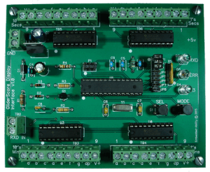
 The GliderScore Display Interface is an embedded processor-based board designed to be directly connected to a serial port or USB-to-serial adapter on a computer that is running the popular GliderScore scoring application for RC soaring contesting. The Display Interface accepts commands from GliderScore and displays competition event time in minutes:seconds format on four outdoor LED display digits. It also supports a Round-Group display: boards can either periodically interleave the current Round and Group numbers with time counts or a board can be configured to always display just Round-Group information. Very flexible!
The Display Interface board supports a wide variety of common-anode LED display boards that the user purchases separately depending on their site and visibility needs (see LED Display Sources page for details). The GliderScore Display Interface product is carefully designed for minimum power consumption in battery-operated and portable wireless environments but works equally well in AC-equipped environments.
A typical GliderScore Display Interface system is comprised of the following components:
1. The processor-based Display Interface board,
2. Four 7-segment LED display boards, and
3. A 12v battery or DC power supply.
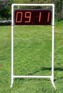
LED display (9″) on PVC stand
Features
- Converts GliderScore timer display commands into an external LED interval timer display
- Supports GliderScore’s Extended Protocol for display of Round and Group information in addition to timer values
- Runs in AC-powered and battery-powered environments
- Supports a wide variety of commercially available LED display boards
- Non-multiplexed LED drivers for maximum possible display brightness
- Two versions of the board are available: the Standard option has 150mA/segment drivers which is the most-often used; the High Current option has 350-400mA/segment drivers for larger displays.
- Low power processor-based interface board
- On-board discrete LED status indicators:
– RXD: Serial command received
– ERR: Command error detected (serial command overrun, wrong baud rate,etc ) - Serial baud rates supported: 9600 or 19200 baud
- “Battery saver” mode that blanks leading zeros and saves ~25% power (ideal for fully portable wireless use)
- Comprehensive User Guide covers interface board and LED display installation tips and techniques
Specifications
- Board dimensions: 119.7 x 98.5mm (4.7″ x 3.9″). Height of components on board 18mm (0.7″) max.
- Input power requirements: 7-16VDC @ 50mA max (not including external LED display current requirements). Typical current load = 25mA.
- Operating Temperature: -10 to 65 degrees C (15 to 150 degrees F)
- GliderScore command formats supported:
Standard “Embedded-Ability” format: “Ammss+CR”
ASCII character string “Ammss \r” (the letter A, the minutes digits,
the seconds digits, the ASCII character for Carriage Return).
Extended Protocol format: “R99G99TmmssAA+CR”
R99 – 99 is the round number.
G99 – 99 is the group number.
Tmmss, there “mm” is 2 digits for minutes
and “ss” is 2 digits for seconds.
AA – Two character code for timer state: PT prep time, WT working time,
LT landing time, ST sleep time, DT display time-of-day.
CR – ASCII Carriage Return. - Serial port configuration: Selectable baud rate = 9600, 19200. Always 8 data bits, 1 stop bit, no parity. Only the receive data line is monitored, all other serial port signals are ignored.
- USB to Serial adapter recommendation: Sabrent USB to RS-232 DB9 (Prolific chipset) on Amazon
- Serial port cabling length: If you are directly connecting via a cable to your scoring computer:
Max. recommended for shielded or unshielded non-twisted pair cable is:
15 meters (49 ft) @ 9600 baud, or
7.6 meters (25 ft) @ 19200 baud.
Max. recommended for twisted-pair cable (e.g. CAT5e):
60 meters (197ft) @ 9600 baud, or
30 meters (99ft) @ 19200 baud. - Supports Wireless display options that are commonly used.
- External LED display current limits: Standard board with 150mA per segment drivers is the most-often used, and the High Current board with 350-400mA per segment drivers for larger displays (each 7-segment display digit has 7 segments plus the decimal point).
- External LED display voltage supply limits: 50V absolute maximum, 24v max recommended.
- External LED display configuration supported: Common-anode only (open drain drivers electrically connect to ground to illuminate a digit segment).
- Input terminals: RXD IN+/- (transient and over-voltage protected), V+/GND (reverse polarity protected).
- Output terminals: 10’s Minutes (9 wires), 1’s Minutes (9 wires), 10’s Seconds (9 wires), 1’s Seconds (9 wires).
Power Consumption Considerations
| Item | Power Supply Current Requirements @ 12v |
| Interface board only |
25mA typical, 30mA typ. with ERR LED lit. |
| (4) LED 7-segment display digits |
Depends on the size of LED digits in your installation. To estimate the worse-case current consumption multiply 8 segments (7 segments plus decimal point) by the per-segment current for the maximum rated digit current. Example 1 – Using Qkits MXA-004 Ultrabright 9” LED boards
Current consumption values for non-ultrabright LED boards are pretty much the same. “Worse-case” example – Four 7-segment LED display boards and a per-segment current consumption at a worse-case rating of 60mA at 12v. 4 digits x 8 segments x 60mA = 1.9A worse case. So adding in the interface board current we have just over 2A of worse case current. Since the average number of segments per digit that are illuminated is on the order of 5, you could safely use a 12v DC power source rated at 1.2A. |
| Battery size guidelines | To run your LED display on battery power, assuming 60mA of current per segment and assuming that the Battery Saver option JP1 is installed, you can figure a conservative 1.2AH of battery capacity for every hour you run the display. For a full contest we like using a small 12v 12aH gel cell battery. |